modする為の自分用の覚書メモ
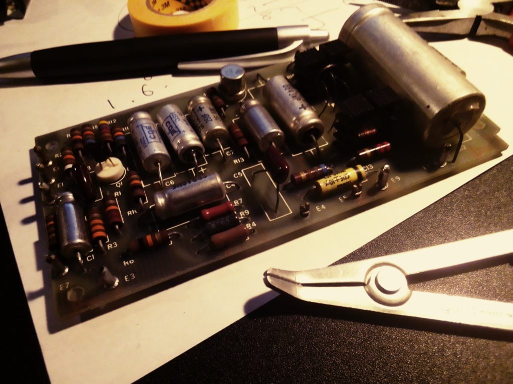
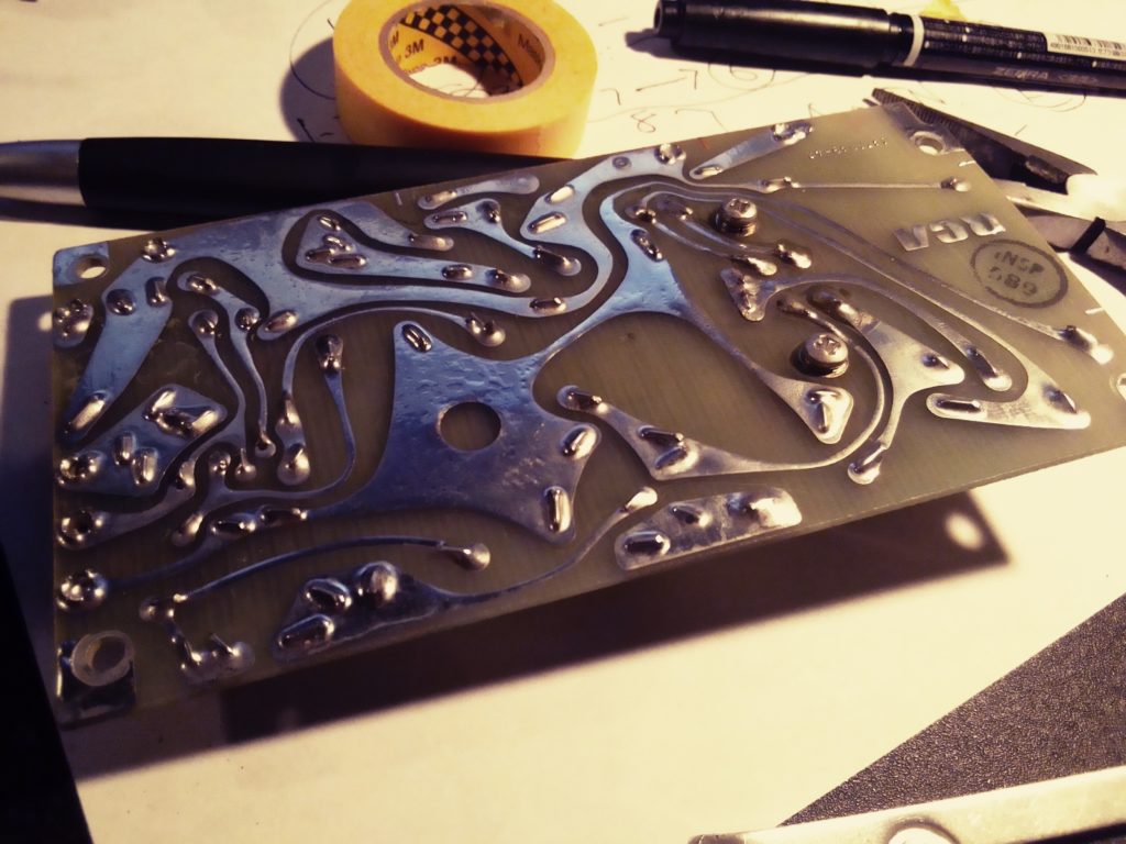
基盤スポット
E1= Input trans + (T101/9) PIN#2 [gain pod out]
E2= Input trans – (T101/8)
E3= Ground (“G” on schematic)
E6= Comm on Power source (“B” on schematic)
E7= -30V (“P” on schematic)
E8= To Output trans T102/1 (“O” on schematic)
E9= To Output trans T102/2 (“T” on schematic)
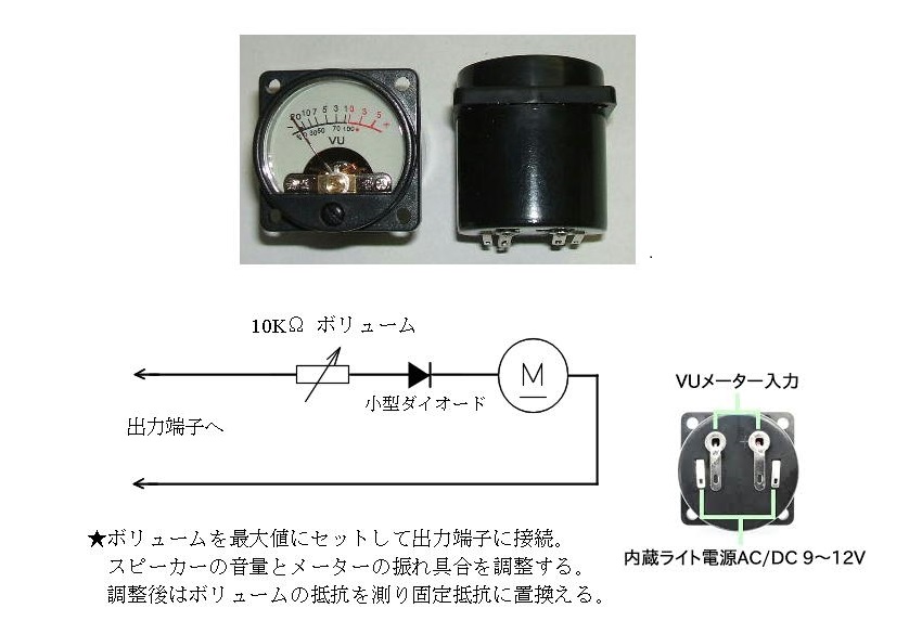
ピンアサイン(male)[female]
PIN#1 Input trans 2nd out + (T101/9)[to gain pod in]
PIN#2 E1 (“H” on schematic)[to gain pod out]
PIN#3 Input trans 3 CT (T101/3)[to flip sw 150/600 center 上]
PIN#4 > not used
PIN#5 600 balance out SEC Output trans T102/4 [to flip sw 位相 center 上]
PIN#6 E6= Comm Power source
PIN#7 Ground (E3 not connected)
PIN#8 Balance in (T101/1)
PIN#9 > not used
PIN#10 > not used
PIN#11 Input trans 4 CT (T101/4)[to flip sw 150/600 center 下]
PIN#12 > not used
PIN#13 600 balance out SEC Output trans T102/7 [to flip sw 位相 center 下]
PIN#14 E7 = -30V (“P” on schematic)
PIN#15 Balance in (T101/2) =CT
PIN#16 Balance in (T101/6)
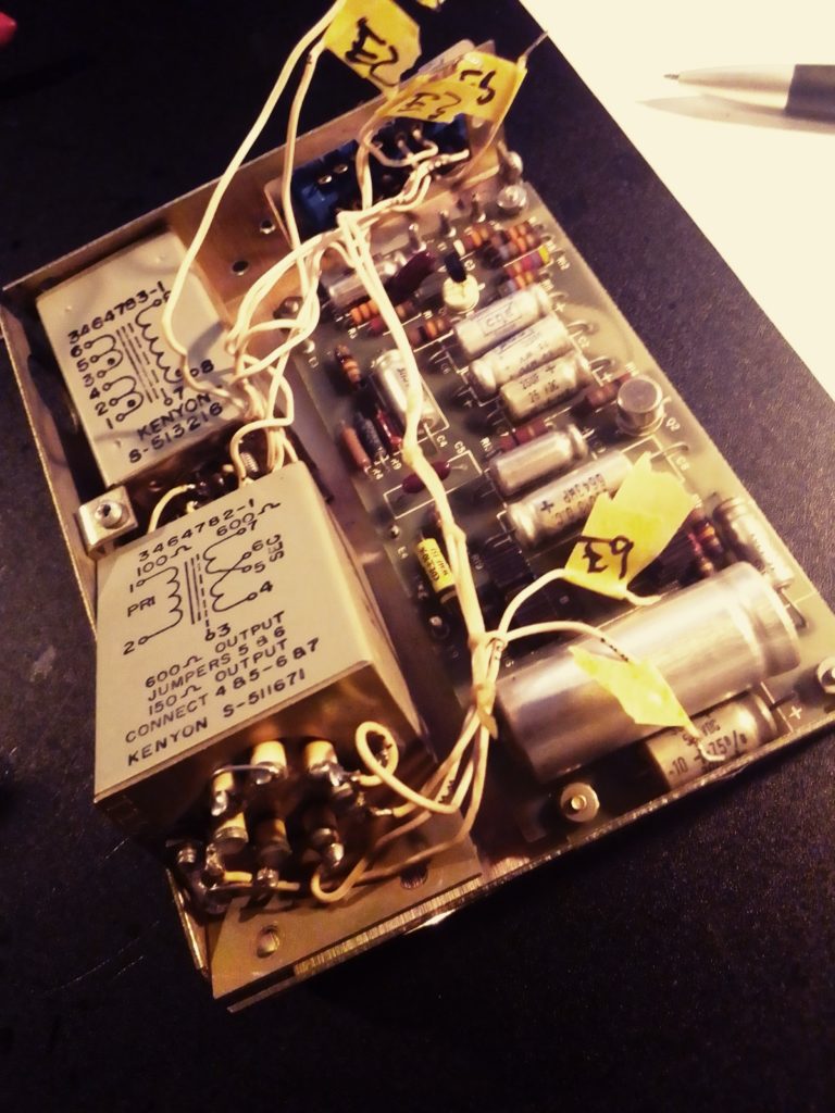
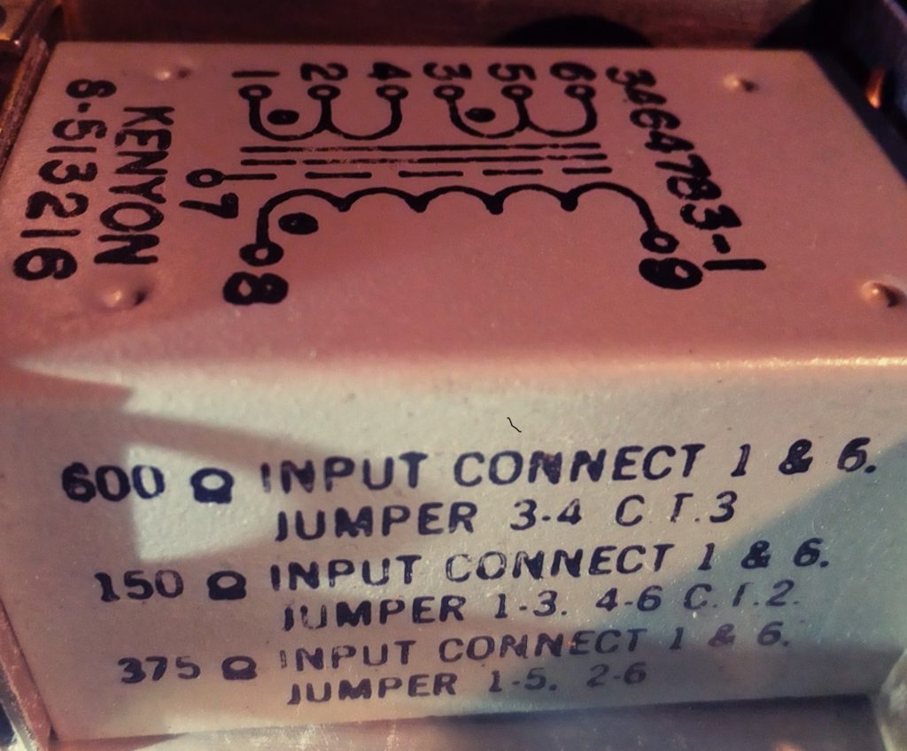
インプットトランス
1番6番 入力
3番4番が150/600切り替え
8番9番が出力
その他のタップは切断
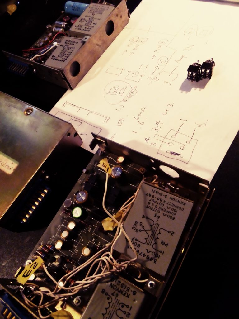
ユニットへの作業
- バラし、基盤PIN 各Eへの配線を外す(ケーブルをマーキングする事)
- バラし、基盤を外す(ネジ一式は戻す事)
- バラし、ケーブルの結束分解、インプットだけ外す (ネジは戻す事)
- インプット各ジャンパー外す
- インプットのケーブル配線コネクターへ (3番から PIN#3 ,4番から PIN#11 )
- ケーブルマークE1(T101/9)を PIN#1 配線コネクター へ
- PIN#2 配線コネクターからケーブルを E1 とマーキング
- その他インプットへの配線は放置、7番のアースへの接続確認、インプットを戻す
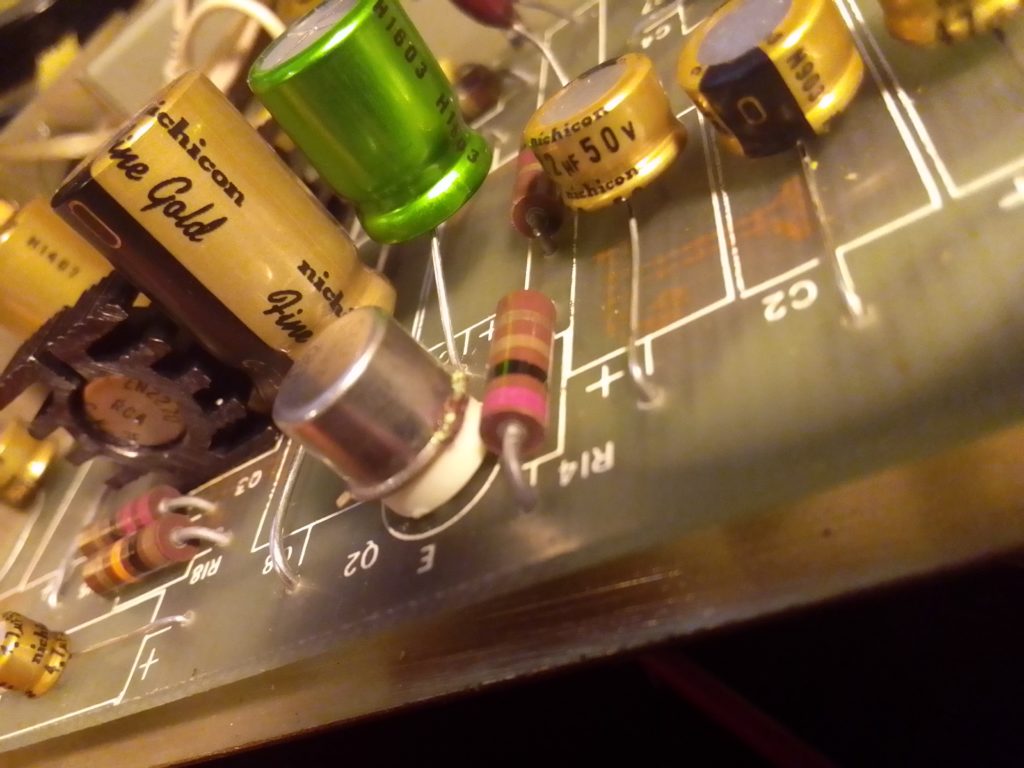
- 基盤のリキャップ、シャーシへ戻す
- 基盤PIN 各Eへの配線、固定用穴